Table of Content
You can also explore different PCB projects from their Open-source community pcbway.com/project/. Please refer to the following article to add the devices with the ESP RainMaker app. In the Tutorial video, I explained all the steps to program the ESP32 using Arduino IDE. In the ESP RainMaker tutorial video, I have covered the following steps in detail. Matter API Allow your Android apps to commission and share Matter devices using Google Play services.
Please refer to the above circuit diagram to connect all the AC appliances and switches with the PCB. After uploading the code to ESP32, please refer to the following article to add the devices with the ESP RainMaker app. In the code, I have used Preferences.h library to remember the last states of all the GPIO connected with relays. Please refer to the following article on the ESP32 Preferences library.
ESP32 Arduino IoT Relay Control with Google Home, Alexa and Manual Switch
You will be redirected to Google and Adafruit for permission to connect these accounts. If you want to turn your lights off as well just repeat these steps but with different activation phrases and "OFF" as a value. Then choose 'Say a simple phrase' from the drop down. I added a Toggle to my dashboard turn my ledstrip on and off and linked this to my feed. The output pin of the IR receiver is connected with D35. I do love to make different DIY electronics projects & share it on my YouTube channel Tech StudyCell.
You can control appliances with Google Assistant from anywhere in the world through the internet. You have to update the main code with these HEX codes. In the tutorial video, I have covered the following steps in detail. In the circuit, I have used D23, D22, D21, D19, D18, D5, D25 & D26 GPIOs to control the 8-channel relay module.
Step One Blynk App:
I have used a 5V 5Amp mobile charger to supply the circuit. I have used the INPUT_PULLUP function in Arduino IDE instead of using the pull-up resistors with each push button.
First, get the HEX codes of unused IR Remote buttons, then update the HEX codes in the code. In the main sketch, update the HEX code of the IR Remote buttons . Please take proper safety precautions while connecting the AC appliances. Please share your feedback on thisESP32 projectand also let me know if you have any queries.
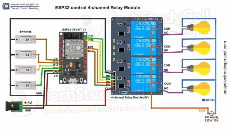
Circuit of the ESP32 Home Automation project
In the “Then That” section select webhooks and configure it accordingly. Download IFTTT mobile application or go to the website sign up to IFTTT with your email or Google account and get started. Connect the relay Module to the ESP32 Board at pin 25 and 26. Now choose the ON state to 0 and OFF state to Logic 1, this is an active-low logic signal. Select the mode to switch instead of the push-button. Click on the “+” icon and add a button from widgets, here you will find various types of widgets.
This is a complete home automation solution you can control a large number of devices via these applications, all you need is to modify the code for new connections. Also, you can buy paid plans for those applications where you will get some extra features. This is a little big project if you are a beginner to the world of IOT based projects. Here we will use different platforms and integrate them to make our home automation system.
The circuit is very simple, I have used D23, D22, D21 & D19 GPIO to control the 4-channel relay module. Make simple IoT-based Projects using ESP32 to control Relays with Google Assistant and Alexa with voice commands. With this ESP RainMaker home automation project, you can also monitor the real-time sensor readings like Temperature, Humidity, and LDR on the ESP RainMaker app. These are specialized IoT platforms to offer the customers the most commonly used features, such as adding a timer or monitoring the current consumption.
At the end, select your desired language and click on “Create Trigger”. While uploading, press and hold the “Boot” button to correctly upload the code on ESP32. Click on “Edit Layout”, then, click on “Block Info” in the settings section. The last part of the “API URL”, meaning “/feed/led”, must be written in a part of the code.
Here, I have used the free Sinric Pro account, so I can add a maximum of 3 devices for free. I have used their services for my different electronics projects, I always received the PCB on time and the quality is very good in this reasonable price range. So, you can easily make this home automation project at home just by using an ESP32 and relay module.
I will really appreciate it if you share your valuable feedback. Also if you have any query please write in the comment section. Thus, all the devices from Sinric Pro will be added to Google Home Account. First, download the code & install all the required libraries mention in the code. APP SECRET for the account, which will be required in the code.
By following all these steps, you can now use Google Assistant and Alexa to control your appliances. I have covered all the following steps in the tutorial video. Now, If you use pushbuttons instead of switches, then refer to the following circuit. Create your first applet, click on create then select “If This” condition, and then select Google assistant.
I hope you have liked this electronics project, Thank you for your time. For more information, visit the GitHub page of Sinric Pro. We recommend downloading the most recent versions of these libraries from the provided links. After that, install the libraries at Arduino IDE – Sketch – Include Library – Add Zip Library. PCBway is a very well-known PCB manufacturer for various types of PCB boards at very reasonable prices. They not only produce FR-4 and Aluminum boards, but also advanced PCBs like Rogers, HDI, Flexible and Rigid-Flex boards.
Connecting Devices With Alexa
In fact, the IFTTT acts as a communication interface between them. In this instructable I will explain how to connect your Google Home to your ESP8266 board. The end goal is to switch my ledstrip on and off with voice commands. Please take proper safety precautions while connecting the appliances with the relay module. Connect the 4 home appliances with the relay module as per the circuit diagram.

No comments:
Post a Comment